Wind tunnel cross section :
2.3*1 meter
Turn table diameter :
1.83 meter
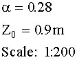
Using a modified spires/roughness configuration a neutrally
stratified boundary layer was modelled
Profile :
|
Wind tunnel cross section :
Turn table diameter :
Using a modified spires/roughness configuration a neutrally
stratified boundary layer was modelled
Profile :
|
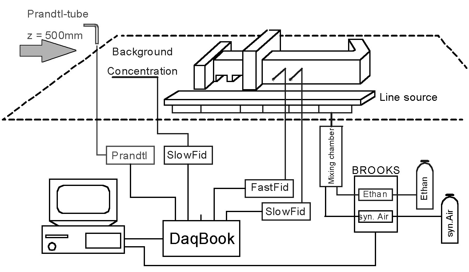
Wind tunnel set-up
Emissions from vehicular traffic were modeled by a continuous line source consisting of about 2400 capillaries per lane. Using 42 mm long hypodermic needles with an inner diameter of 0.2 mm as capillaries, a uniform release of tracer along the line source could be realized even for small source flow rates, preventing the source from generating a significant momentum.
Measurement set-up
The source flow was controlled by laboratory grade mass flow controllers (BROOKS Valve Series 5850S) that have been checked against independent volumetric standards (BROOKS Volumeters). For immission measurements a fast flame ionization detector (FastFID, Cambustion Ltd.) as well as several slow FID's (Rosemount Analytical) have been used. Installing the sampling head of the FastFID inside the model buildings, very short sampling tubes could be used during measurements. As a result, a frequency resolution of up to 230 Hz was realized, capturing the instantaneous character of the dispersion sufficiently. Reference wind speeds were measured independently by a Prandtl-tube/pressure transducer setup as well as a hot-wire anemometer (TSI Inc.). Checking and calibrating all devices affecting the quality of the measurements, a repeatability of better than 3% for most of the measurements was reached.